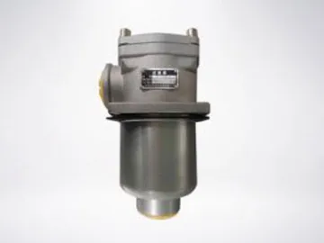
Return Filters
The return filters are designed for fine filtration of the return oil in hydraulic systems. They can keep the return oil clean by removing the outside contaminants or progressive contamination caused by the wear of components, such as fibers, slag, rubber particles of sealing wear and metal particles of parts wear.
| Filter Model | Nominal Flow Rate (L/min) | Filtration Rating (μm) | Diameter(mm) | Pressure Drop(MPa) | Clogging Indicator | Weight (Kg) | Filter Element Model | ||
| Initial | Max. | (V) | (A) | ||||||
| RF-60×*L- | 60 | 1 3 5 10 20 30 | 20 | ≦0.07 | 0.35 | 12 24 36 220 | 2.5 2 1.5 0.25 | 0.4 | HL0060R*BN/HC |
| RF-110×*L- | 110 | 0.9 | HL00110R*BN/HC | ||||||
| RF-160×*L- | 160 | 40 | 1.1 | HL001600R*BN/HC | |||||
| RF-240×*L- | 240 | 1.8 | HL00240R*BN/HC | ||||||
| RF-330×*L- | 330 | 50 | 2.3 | HL00330R*BN/HC | |||||
| RF-500×*L- | 500 | 3.2 | HL00500R*BN/HC | ||||||
| RF-660×*L- | 660 | 80 | 4.1 | HL00660R*BN/HC | |||||
| RF-850×*L- | 850 | 13 | HL00850R*BN/HC | ||||||
| RF-950×*L- | 950 | 90 | 20 | HL00950R*BN/HC | |||||
| RF-1300×*L- | 1300 | 100 | 41.5 | HL001300R*BN/HC | |||||
Connections
| Model | Dimensions(mm) | ||||||||||||||
| B1 | L | L1 | h | D1 | H | D | d | M | B | M1 | t1 | m | t3 | DN | |
| RF-60×*L- | 90 | 166 | 92 | 11 | φ80 | 34 | φ100 | φ5.5 | M27×2 | 48 | M27×2 | 16 | |||
| RF-110×*L- | 233 | 159 | M33×2 | M33×2 | |||||||||||
| RF-160×*L- | 120 | 209 | 120 | 11 | φ106 | 40 | φ135 | φ7 | M48×2 | 66 | M48×2 | 20 | |||
| RF-240×*L- | 268 | 179 | M48×2 | M48×2 | |||||||||||
| RF-330×*L- | 152 | 271 | 138 | 13 | φ135 | 63 | φ170 | φ9 | M60×2 | 85 | M60×2 | 27 | |||
| RF-330×*F- | M60×2 | M12 | 23 | φ50 | |||||||||||
| RF-500×*F- | 351 | 218 | |||||||||||||
| RF-660×*F- | 411 | 243 | 13 | φ175 | 83 | φ220 | φ13.5 | 110 | M16 | 22 | φ80 | ||||
| RF-850×*F- | 492 | 324 | |||||||||||||
| RF-950×*F- | 449 | 251 | 14 | φ208 | 93 | φ290 | φ17.5 | 135 | 22 | φ90 | |||||
| RF-1300×*F- | 573 | 332 | 121 | 145 | φ100 | ||||||||||
Scan QR to Read
Links:https://globefindpro.com/products/8037.html
Links:https://globefindpro.com/products/8037.html
Recommended Products
-
 Mining
-
 Self-Cleaning Filter
-
 Lift Hydraulic Cylinder
-
 Air Filter Element
-
 Duplex Filter
-
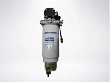 Fuel Water Separators/Oil- and Liquid Separators/Oil & Water Separation Filter
-
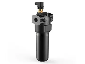 High Pressure Filters
-
 Metallurgy
-
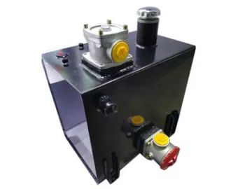 Hydraulic Tank
-
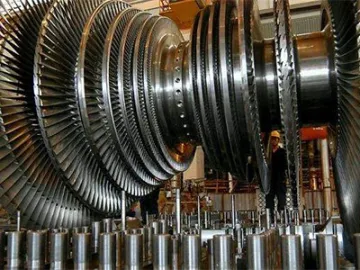 Electrical Power Systems
-
 Outward-Opening Window, Aluminum Window
-
 Aluminum Sliding Glass Door, GDM130
Hot Products
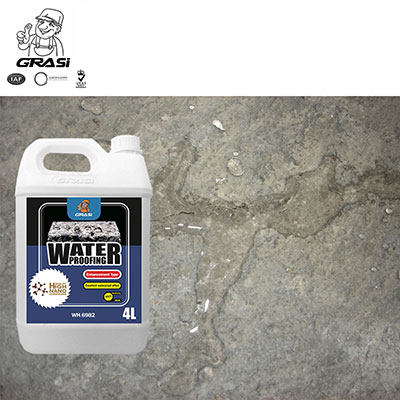 WH6982 Concrete Mortar Waterproof Penetrant for Porous Construction Materials (Emulsion Enhancement Type)
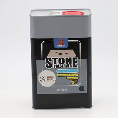 WH6989 Stone Curing Agent for Marble Granite Sandstone Limstone (Stain Resistant Special Effect Type)
