Roll Forming Machine
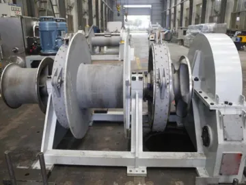
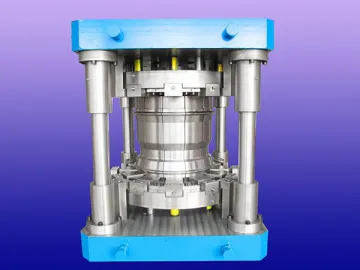
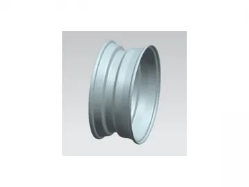
The roll forming machine is also known as a wheel rim forming machine, and is used for symmetrical or asymmetrical roll forming of steel wheel rims. Theroll forming equipment consists of the main machine, hydraulic transmission system, pneumatic system, PC control system and lubrication system.
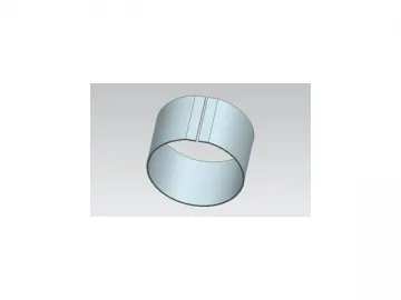
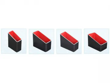
Generally, small rim lines and large rim lines carry out 3 processes to complete the rim profiling. Each process uses one set of roll forming machines. However, the ultra-large line completes the rim roll forming operation through 4 processes. The 4th presses the roll press into a non-skid pattern.
Process Pictures for Reference
1st Process: Roll Forming
2nd Process: Roll Forming 3rd Process: Roll Forming 4th Process: Non-skid pattern rolling
Main Features
1. The forming dies on this wheel rim roll former comes with an easy to dismount design which ensures a quick change of the die, controlling the changing process to take only about 30 minutes.
2. Both the small and large wheel rim lines often use 3 roll forming machines that share one set of automatic load and unload mechanisms. These systems use a 3 process and 4 location design, which saves time and improves production efficiency.
3. The split design between the load/unload unit and the main machine allows for both manual and automatic operations.
4. The roll forming dies can be designed to be symmetric or asymmetric according to processing demands.
5. The upper and lower shafts are hydraulic driven. During the rim profiling, the rotating speed of the upper and lower rollers can be automatically adjusted.
6. The shafts can be adjusted at both dip angles and axial directions. This makes each part of the roller surface uniformity stressed, ensuring the precision.
7. The space between the upper and lower spindle is adjustable, as is the feeding speed.
8. The stroke of a side guide rail is also adjustable.
Optional Device for Quick Changeover of Die
Automatic Load and Unload Mechanism with a design of Three-Process and Four-Location
Main Technical Parameters of Roll Forming Machine
| No. | Items | Parameters | |||
| 1 | Model | GX-23/300 | GX-45/600 | GX-48/800 | |
| 2 | Roll forming force | 230KN | 400KN | 500KN | |
| 3 | Motor power of hydraulic system | 62.5Kw | 82.5Kw | 165Kw | |
| 4 | Length of mould on spindle | 350mm | 670mm | 900mm | |
| 5 | Upper and lower spindle speed | 220r/min | 200r/min | 200r/min | |
| 6 | Spindle material and diameter | 40Cr, 140mm | 40Cr, 200mm | 40Cr, 220mm | |
| 7 | Space between upper and lower spindle | 240~380mm | 340~480 | 380~520 | |
| 8 | Lower spindle stroke | 140mm | 140mm | 140mm | |
| 9 | Adjustable range of lower spindle feeding speed | 2~10mm/s | 2~10mm/s | 2~10mm/s | |
| 10 | Adjustable dip angle of lower spindle | -0.35 ° ~0.17 ° | ±0.35° | ±0.35° | |
| 11 | Side guide roller (Linear) | Stroke | 100mm | 140mm | 160mm |
| Adjustable stroke | 50mm | 50mm | 50mm | ||
| 12 | Max. diameter of guide roller | 200mm | 220mm | 240mm | |
| 13 | Rated input voltage | 380V | 380V | 380V | |
| 14 | Rate input current | 62.5Kw | 82.5Kw | 165Kw | |
| 15 | Power cord section (copper) | Single core 70mm2 (3 2) | Single core 90mm2 (3 2) | Single core 180mm2 (3 2) | |
| 16 | Consumption of hydraulic cooling water | 2000L /h | 3000L /h | 4000L /h | |
Links:https://globefindpro.com/products/42580.html
