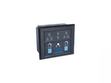
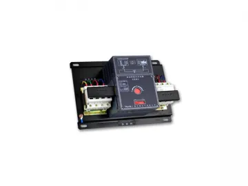
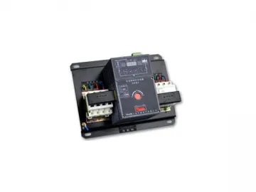
Controller
Controller
| Model | Function | Matchable model |
| ZCU-A | Detection of over-voltage, under-voltage and the lack of phase fault of two lines power supply | ZCU-××N. ZCU-××T. ZCU-××M. ZCU-××Q |
| ZCU-B | Detection of over-voltage, under-voltage and the lack of phase fault of two lines power supply; control generators and incorrect operation | ZCU-××N. ZCU-××T. ZCU-××M. ZCU-××Q |
| ZCU-C | Detection of over-voltage, under-voltage and the lack of phase fault of two lines power supply; control generators and incorrect operation | ZCU-××TN(Out of supplying) |
| ZCU-D | Detection of over-voltage, under-voltage and the lack of phase fault of two lines power supply; control generators and incorrect operation | ZCU-××C Namely(ZCU-××N. ZCU-××with wire connection ) |
Connection Terminals Diagramof ZCU-A-type Controller:
-A1, B1, C1, N1 connect three-phase four wire system of main power supply, ifconnected three-phase three wire,N1 grounding.
-A2,B2,C2,N2 connect three-phase four wire system of stand-by power supply, ifconnected three-phase three wire,N2 grounding.
- L1 connects the main power phase A through the auxiliary contact in theswitch; it is the main power brake indicator.
- L2 connects the stand-by power phase A through the auxiliary contact in theswitch; it is the stand-by power closing indicator.
-M1, M2, M3, M4 are out-put terminals of switch.
Brief Functional Introduction of ZCU-B-typeController
Compatible with all the function of ZCU-A-type controller;
Adding over voltage detection of two-path power;
Providing generators start signal (delayed about 3 S to issue when a main powerfails), When you order, please indicate electricity grid – Generators.
Main Characteristics of ZCU-A-typeController:
Adopt single chip to stop program control ;
Logical program and electric dual linkage;
Compact design make it available to be placed in switch cabinet panel forobservation, operation and running;
A strong anti-electromagnetic interference performance.
Connection Terminals Diagram of ZCU-B-typeController:
-A1, B1, C1, N1 connect three-phase four wire system of main power supply , if connected three-phase three wire,N2 grounding
-A2,B2,C2,N2 connect three-phase four wire system of stand-by power supply, ifconnected three-phase three wire,N2 grounding
-When L1 connects the main power phase A through the auxiliary contact in theswitch, the main power will close.
-When L2 connects the stand-by power phase A through the auxiliary contact inthe switch, the stand-by circuit will close.
-M1, M2, M3, M4 are switching out-put terminals.
-F, F1, F2 are generator start signal output terminals, F is the publicterminal, when the main power is normal, F will closes with F2, F and F1disconnect ;when the main power become abnormal and the stand-by power has nopower , F and F1 will close after three seconds , while F and F2 willdisconnect.
Brief Functional Introduction of ZCU-C-typeController:
ZCU-C-type controller used to control the three segments TN type ATS thatcomposed of three coins.
A dedicated cable used to connect the switch and the controller and makes iteasy to install;
Detect the two-path power over-voltage, under-voltage, lack phase, ect;
Make the TN-type ATS disconnect the two-way power at the same time, convenientto overhaul;
Provide generators start signal (delayed about 3 S to issue when the main powerfails).
Connection Terminals Diagram of ZCU-C-typeController:
-F1, F, F2 are used to start generator, F is the public terminal, when the mainpower is normally closed, F2 is normal-shut terminal; when the main powerbecame abnormal, it will delay about 3 S to close;
-When R1, R2 are connected, the controller will be in unallowable state: (R1,R2 can only connect passive contact, or it will damage the controller);
-L1, L2 can be added more functions according to the request of users(standby).
Unallowable State of ZCU-C-type Controller:
When R1, R2are connected, the controller will be in an unallowable state, andthen the lights will flash at the same time.
1. When connecting terminals R1, R2 means to press a manual reset button andthen it will be in unallowable states, at this time, controllers will notrespond no matter how to press main power transform button, backup powertransform button or even returning to the automatic mode.
2. In automatic mode, connecting terminals there is no place for R1, R2, toreset, and just be in unallowable state but not respond to external conditions.
3. Cutting off the two-path power, and connecting terminals R1, R2 makes thecontroller in unallowable state to avoid dangers to maintainers by misusing.
Brief Functional Introduction of ZCU-D-typeController:
ZCU-D-type controller used to control the two segments TN type ATS composed oftwo coins.
A dedicated cable used to connect the switch and the controller and makes iteasy to install;
Detect the two-path power over-voltage, under-voltage, lack phase, etc.
Provide generators start signal (delayed about 3 S to issue when the main powerfails).
Connection Terminals Diagram of ZCU-D-typeController:
-F1, F, F2are used to start generator, F is the public terminal, when the mainpower is normally closed, F2 is normal-shut terminal; when the main powerbecame abnormal, it will delay about 3 S to close;
-When R1, R2 connect, the controller will be in unallowable state: (R1, R2 canonly connect passive contact, or it will damage the controller)
-L1, L2 can be added more functions according to the request of users(standby).
Links:https://globefindpro.com/products/57516.html
-
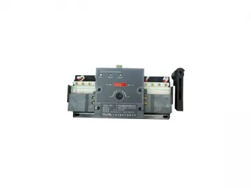
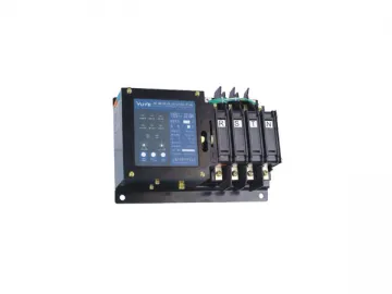 ZGS1-32NA Automatic Transfer Switches (ATS)
-
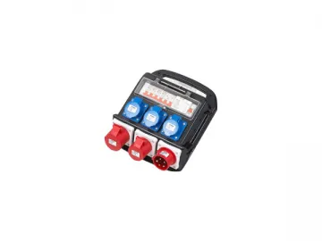
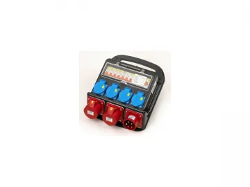 Distribution Box DCMB09-2
-
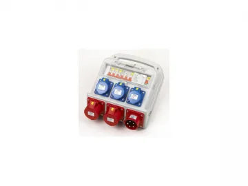 Distribution Box DCMB09-2
-
 ZGQ1-CA Automatic Transfer Switches (ATS)
-
 Distribution Box DCMB01-4
-
 ZGQ1Y-63 Automatic Transfer Switches (ATS)
-
 ZGQ1-CB Automatic Transfer Switches (ATS)
-
 AGE Three-phase Asynchronous Motor
-
 AGC Three-phase Asynchronous Motor
-
 Load Isolating Switch D Series
-
 AGD Three-phase Asynchronous Motor
-
 Distribution Box DCMA10-2