Water Well Screen for Sand Control
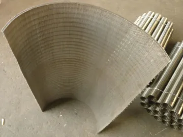
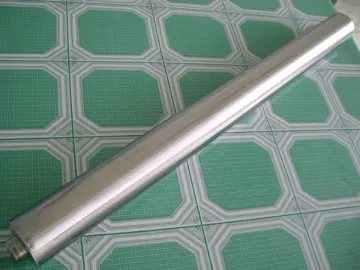
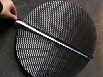
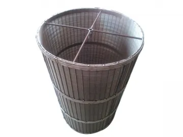
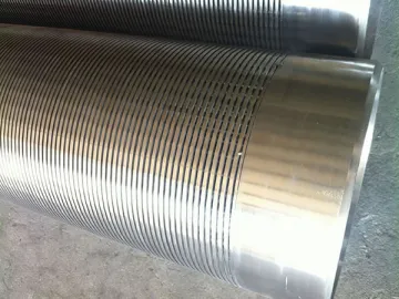
Screen slot design is a crucial aspect in the efficiency of production wells. Precise slot control starts with precise slot forming. Because of that, Hengyuan wedge wire screen is constructed by helically winding a continuous triangular shaped wire around a series of vertical support rods, ensuring the final screen slot will meets our strict quality standards.
Sand control is another crucial aspect in well management. Excess sand in pipes leads to premature pumping equipsment failure. Thanks to a unique slot design, sand has a smaller chance of entering through the screen, which leads to a smaller chance of clogging or abrasions. With the wedge wire screen, a larger amount of water can easily enter the well pipe, which means increase in well productivity. Due to these factors, Hengyuan’s water well screens are widely used in well completion, geothermal well construction, and remedial construction work.
Benefits of the Wedge Wire Screen
1. Maximum Flow Rate
The slots are arranged in a uniform pattern, allowing water to enter the screen directly from all directions of the water bearing area.
2. Excellent Sand Control Performance
Traditional perforated tubes have holes large than 1 cm, which do not keep sand out. Scratches and corrosion on the outer wrap layers leads to more sand, gravel and clay entering the well pipe, which in turn leads to clogging. However, the wedge wire screen has slot openings between 0.5mm and 1.5mm, keeping most sand and abrasive particles out.
3. Long Well Life
Each wedge wire screen undergoes anti-corrosion treatments, rendering it less prone to rust or encrustation.
4. Easy Installation
Wedge wire screens are lighter than cast iron pipes or perforated tubes, making them easier to install.
5. Standard Length
The standard length of each wedge wire screen is 3.2m. Pup joints can be added upon request.
6. Connection Method
Welded, threaded, and flanged connections are available.
Applications for the Wedge Wire Screen
This screen is applicable in vertical wells, deviated wells, directional wells, and others that require sand control.
Main Specifications
| Diameter (mm) | Wall Thickness (mm) | Coupler Outside Diameter (mm) | |||||||||||
| 4 | 6 | 8 | |||||||||||
| φ127 | √ | φ127 | |||||||||||
| φ159 | √ | √ | φ159 | ||||||||||
| φ168 | √ | √ | φ168 | ||||||||||
| φ219 | √ | √ | φ219 | ||||||||||
| φ273 | √ | √ | φ273 | ||||||||||
| φ325 | √ | √ | φ325 | ||||||||||
| φ426 | √ | √ | φ426 | ||||||||||
| φ529 | √ | √ | φ529 | ||||||||||
| φ630 | √ | √ | φ630 | ||||||||||
| Wall Thickness (mm) | 4 | 6 | 8 | ||||||||||
| Slot Size (mm) | 1 | 1.5 | 2 | 3 | 1 | 1.5 | 2 | 3 | 1 | 1.5 | 2 | 3 | |
| Percent Open Area (%) | 8.8 | 13.9 | 18.8 | 30.4 | 6.3 | 9.5 | 12.7 | 20 | 5.6 | 8.6 | 11.4 | 16.9 | |
Links:https://globefindpro.com/products/59298.html
