CD60 Series Starting Capacitor
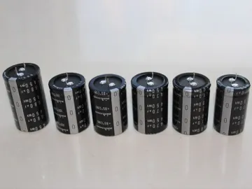
Our CD60 series starting capacitor, as a kind of aluminum electrolytic capacitor, use high purity electronic aluminium foil as the two electrode plates. It can reduce the voltage on the leading-out terminals from the peak of rated value to 50V or lower in 60s since the moment when the power is cut off. The discharging resistance is quite large. It can be used for intermittent load such as the starting of automobiles. The firm enclosure is convenient for the installation. In addition, the capacitors are up to the DIN EN60252-1 standard.
Tips
1. The CD60 starting capacitors are supposed to be installed at places no more than 2000m in altitude and with air condition better than API Class II;
2. The residue voltage should be no more than 10% rated value when the capacitor is put into use.
| Model: CD60-B (Application: motor capacitor) | |
| Structure | |
| Dielectric | Al2O3 |
| Electrode | aluminium foil and electrolyte |
| Embedment | Polycarbonate shell |
| Connecting terminal | American type: 2 2 type soldering terminals (6.3×0.8) |
| Discharge resistance | It can reduce the voltage on the leading-out terminals from the peak of rated value to 50V or lower in 60s since the moment when the power breaks. |
| Installation | Flat base, M8 stud |
| Dimension | Diameter: 36.5-64mm, Height: 70-111mm |
| Technical parameter | |
| Rated capacitance, CR | 20μ f ~ 1280μf |
| Rated voltage, VR | 110Vac ~ 330VAC |
| Rated frequency, FR | 50/60Hz |
| Capacitance allowance | ±10%, ±15%, ±20%; (Products with other allowances are also available according to your requirement, i.e. asymmetric allowance) |
| Dissipation(20℃, 100Hz, AC) | 110V, tg6≤0.12; >110V, tg6≤0.10 |
| Temperature | -25℃~ 65℃ |
| Testing data | |
| Electrolytic electric strength test, VTT | The dielectric between the two electrodes can endure 1.2×VR AC testing current, no arc-over will be observed during 2s. |
| Insulation test between the electrodes and the enclosure | 3000V AC power frequency testing voltage in 2s |
| Power factor (25℃, 50Hz) | Up to 10% |
| Durability | Testing voltage: 1.1×VR (±2%)Testing frequency: 50Hz/60HzTesting temperature: 55℃±2℃Testing method: 1s charging, 59s discharging (1.7% relative run time)Test duration: 500h Testing requirements1. No permanent breakdown, break circuit and arc-over are allowed.2. The appearance should be normal after the test. No leakage of the filling substance or other kinds of damage is allowed. The sign should be clear.3. The capacitance change should be in the range of ±10% rated capacitance, while the dissipation tan6 should be less than 0.2 (20℃, 100Hz) |
Application theory
The starting capacitor can provide the auxiliary coil of the single phase motor with leading current. Thus a rotating magnetic field can form between the auxiliary coil and main coil, so a relative big starting torque can be acquired with a relative lower current, making the motor start to work. When the speed of the motor reaches 75% of the rated speed, the capacitor will disconnect the circuit.
Storage of the capacitor
The starting capacitor should be used in one year after the production date. After the first usage, the product shall be tested before its usage. If the necessary test conditions are not available, the capacitor should be loaded with rated voltage for 2s or 3s, then repeat this step for two more times. However, the total recovery time should not be more than 10 seconds. If the capacitor has already connected with the motor, you can achieve the same effect by switching on the motor for two or three times before getting the capacitor loaded.
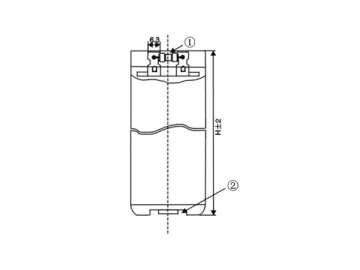
| Model: CD60-B (Application: motor capacitor) | |||
| ① Discharging resistance ② M8 stud with washing and nut | ③ Upper lid④ Type of leading-out terminal from sheathed lines⑤ S type⑥ F type | ||
| ⑦ Air valve (Anti-explosion) | ⑧ Locating ring | ||
| ⑨ Enclosure diameter (D, mm)⑩ Terminal interval (S, mm) | ⒒ Installation ring | ||
Links:https://globefindpro.com/products/76731.html
-
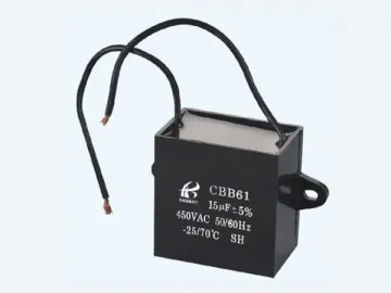 CBB61 Series Polypropylene Film Capacitor
-
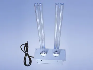 UV Air Purifiers
-
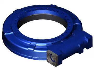 HSE Series Single Worm Slewing Drive
-
 RK Series Four Point Contact Ball Bearing
-
 Ultra-Thin X-Ray Film Viewer
-
 Thrown Silk Yarn
-
 CBB80 Series Dry Capacitor, Immersed Capacitor
-
 CD239 Series High Current Capacitor
-
 Wall Mounted UV Lamp
-
 Movable UV Lamp
-
 Underarm Crutch
-
 Double Ended Germicidal Lamps (Preheat Start) - T6 2P
