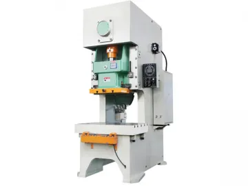
JH21 Series C Frame Press
Feature
1. The body of the JH21 series C frame press is welded by steel plates that have been subjected to tempering technique, so the machine is highly stable and precise.
2. The lengthened six-side rail is adopted for this press machine. The rails are highly anti-wear and precise.
3. The premium overload protection device is sensitive, reliable, and effective.
4. The enclosed bevel wheel of the JH21 series C frame press works stably, and the noise it quite small.
5. The wet clutch is adopted. It can work steadily and produce little noise. Besides, little maintenance is needed.
6. In our JH21 series C frame press, the sliding block is used to connect the pneumatic twin cylinder and thus the sliding block and the upper die can keep balance. Besides, the noise is reduced, and the gap between the connecting rod and sliding block is eliminated. Accordingly, the impact and abrasion that some important components suffered are also greatly reduced.
7. The PLC controlling system of the JH21 series C frame press is quite reliable. As a high precision pneumatic press, this metalworking machine comes with a pneumatic system, which is controlled by a duplex electromagnetic valve. Thus the machine can acquire the inching property, and press individually or continuously.
8. The key components like pneumatic component, electronic components, sealing elements, and buttons are all imported from widely recognized companies.
9. The optional properties of our JH21 series C frame press include air cushion, photoelectric protection, automatic feed, stepless speed control, quick change of die, and so on.
Picture of the details
The high precision gear, high pressure oil cylinder, crank shaft, and the transmission wheel for conveying belt
The mobile double-handed button box, touch screen, cam controller, and overload pump
Standard configuration
1. High performance wet clutch
2. Hydraulic overload protection pump
3. Electric lubricating system
4. Manual lubricating system
5. The balancing cylinder is adopted in our JH21 series C frame press for keeping slide and upper die balance.
6. Interface for the feed fault detector
7. Touch screen
8. Electronic crank shaft angle indicator
9. Cam controller
10. Electronic sliding block adjusting device
11. PLC (program logical controller)
12. Material cast off device
13. Quick joint for air
14. Cushioning pad
15. Work lamp
16. Interface for the pneumatic material removing device
17. Second protection
18. Predetermined counter
Optional device
1. Dry clutch
2. Air cushion
3. Photoelectric curtain
4. Die quick change device
5. Foot pedal type switch
6. Auto-feeding shaft
7. Motor speed controller with variable frequency drive
Technical parameter
| Parameter | Code | Unit | JH21-25 | JH21-45 | JH21-60 | JH21-80 | JH21-125 | JH21-160 | JH21-200 | JH21-250 | JH21-315 | JH21-400 | |
| Nominal capacity | Pe | KN | 250 | 450 | 600 | 800 | 1250 | 1600 | 2000 | 2500 | 3150 | 4000 | |
| Nominal pressure stroke | Sp | mm | 3 | 4 | 4 | 5 | 6 | 6 | 6 | 6 | 7 | 8 | |
| Nominal slide stoke | S | mm | 80 | 120 | 140 | 160 | 180 | 200 | 250 | 250 | 250 | 270 | |
| Slide strokes speed | Fixed | n | Times /min | 100 | 80 | 70 | 60 | 50 | 45 | 45 | 30 | 30 | 30 |
| Variable | 60-100 | 50-80 | 45-70 | 40-60 | 35-50 | 30-45 | 25-45 | 20-30 | 20-30 | 20-30 | |||
| Maximum die set height | H2 | mm | 250 | 270 | 300 | 320 | 350 | 400 | 450 | 500 | 500 | 550 | |
| Die height adjustment | t | mm | 50 | 60 | 70 | 80 | 90 | 100 | 110 | 120 | 120 | 120 | |
| Throat depth | C1 | mm | 210 | 225 | 270 | 310 | 350 | 390 | 430 | 450 | 450 | 490 | |
| Distance between posts | d1 | mm | 450 | 500 | 560 | 620 | 680 | 720 | 900 | 980 | 980 | 1050 | |
| Slide bottom size | Left-Right | a | mm | 360 | 410 | 480 | 540 | 620 | 700 | 880 | 950 | 950 | 1020 |
| Front-Back | b | mm | 250 | 340 | 400 | 460 | 520 | 580 | 650 | 700 | 700 | 750 | |
| Stemhole size | Diameter | d | mm | 40 | 50 | 50 | 50 | 70 | 70 | 70 | 70 | 70 | 70 |
| Depth | I | mm | 65 | 60 | 70 | 65 | 90 | 100 | 100 | 130 | 130 | 130 | |
| Working table size | Left-Right | C | mm | 720 | 810 | 920 | 950 | 1070 | 1170 | 1390 | 1500 | 1540 | 1700 |
| Front-Back | D | mm | 400 | 440 | 520 | 600 | 680 | 760 | 840 | 880 | 880 | 950 | |
| Working table thickness | H3 | mm | 80 | 110 | 130 | 140 | 155 | 165 | 180 | 190 | 190 | 290 | |
| Working table surface height | H1 | mm | 780 | 800 | 900 | 900 | 900 | 900 | 920 | 920 | 1000 | 1100 | |
| Dimensions | Front-Back | A | mm | 1346 | 1435 | 1540 | 1765 | 2040 | 2305 | 2690 | 2660 | 2720 | 2850 |
| Left-Right | B | mm | 945 | 1075 | 1200 | 1200 | 1320 | 1420 | 1540 | 1640 | 1680 | 1750 | |
| Height | H | mm | 2120 | 2391 | 2570 | 2725 | 3035 | 3215 | 3810 | 3785 | 3865 | 4150 | |
| Distance Between Foundation Bolts | Front-Back | a1 | mm | 830 | 950 | 1100 | 1210 | 1510 | 1670 | 2020 | 2150 | 2140 | 2185 |
| Left-Right | b1 | mm | 690 | 745 | 840 | 920 | 1040 | 1140 | 1360 | 1460 | 1500 | 1570 | |
| Motor Power | Power | KW | 3 | 5.5 | 5.5 | 7.5 | 11 | 15 | 18.5 | 22 | 30 | 37 | |
| Approx. weight | KG | 2380 | 3500 | 5150 | 7950 | 10350 | 15400 | 20500 | 23600 | 27600 | 29500 | ||
Links:https://globefindpro.com/products/77077.html
-
 Artificial Butterfly Orchid
-
 Artificial Stellaria Alsine
-
 Artificial Cypress
-
 Plate Bending Roll for Shipbuilding Industry
-
 Z Channel Rolling Machine
-
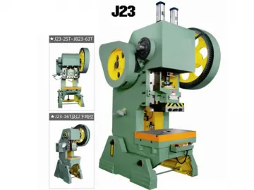 J23 Series C Frame Inclinable Press
-
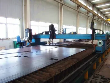 CNC Gantry Cutting Machine
-
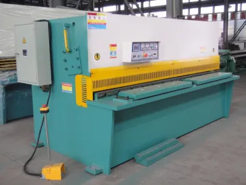 Hydraulic Swing Beam Shear
-
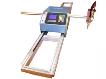 Portable CNC Cutting Machine
-
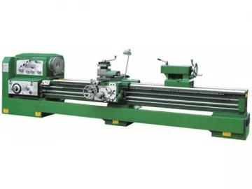 CZ6163A Series Lathe
-
 Hydraulic Section Bending Roll
-
 Universal Plate Bending Roll
