Shell and Tube Flooded Evaporator
The working principle of the flooded evaporator differs from the dry expansion evaporator. Cool water is circulated through tubes in the heat exchanger, while the refrigerant is held in a reservoir, below the tubes. The heat exchanger tubes of the flooded evaporator have a plethora of needle-like perforations on the outer surface, while on the inner side they are contoured to promote enhanced heat transfer. This kind of special heat exchange tube, which both triggers boiling on the outside of the tube and encourages heat transfer on the inside, increases the heat transfer coefficient by an incredible 5 times in comparison with standard tubes.
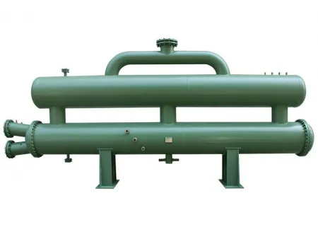
A shell and tube flooded evaporator draws in water and causes the refrigerant to evaporate externally. The liquid refrigerant predominantly fills the shell, ranging between 55 - 65% of the container's overall capacity. This liquid refrigerant then absorbs the heat, transfers to gas, and returns to the compressor via the separator at the top of the cylinder.
Request a Quote Features The flooded evaporator is fitted with a special heat exchange tube that is 1.1mm thick, designed to enhance the heat exchange area. This is achieved through the incorporation of a T-type threaded heat exchanger tube. This device has been awarded a number of national patents due to its unique internal design and structure. Water courses through the pipes, refrigerant is passed through a casing, the heat exchanges between liquid refrigerant, the vaporized gas refrigerant is accelerated straight into the compressor, consequently significantly upgrading heat transferal efficiency. This product is ideal for a range of compressors, including screw, centrifugal, magnetic bearing and more. The efficient structure of the evaporator offers a combination of convenience, ease of operation and management, and a high rate of thermal transfer. Specifications Shell & Tube Flooded Evaporator, Standard Type| Model | Nominal heat exchange capacity kW | Water inlet/outlet inch | Refrigerant inlet inch | Refrigerant outlet inch | Length A mm | Width B mm | Height C mm | Weight kg |
| R22/R134a/R404A | ||||||||
| UCM100A | 352 | 4" | 1-3/8",2-1/8" | 4" | 2837 | 540 | 540 | 617 |
| UCM120A | 422 | 5" | 1-3/8",2-1/8" | 4" | 2837 | 600 | 600 | 630 |
| UCM140A | 492 | 5" | 1-3/8",2-1/8" | 4" | 3446 | 600 | 600 | 767 |
| UCM160A | 563 | 5" | 1-3/8",2-1/8" | 5" | 3446 | 600 | 600 | 791 |
| UCM180A | 633 | 5" | 1-3/8",2-1/8" | 5" | 3446 | 600 | 600 | 815 |
| UCM200A | 703 | 6" | 1-3/8",2-1/8" | 5" | 3446 | 660 | 660 | 798 |
| UCM210A | 739 | 6" | 1-3/8",2-1/8" | 5" | 3446 | 660 | 660 | 810 |
| UCM240A | 844 | 6" | 2-1/8",1-5/8" | 5" | 3446 | 660 | 660 | 844 |
| UCM250A | 879 | 6" | 2-1/8",1-5/8" | 6" | 3446 | 660 | 660 | 856 |
| UCM280A | 985 | 8" | 2-5/8",1-5/8" | 6" | 3446 | 710 | 710 | 903 |
| UCM290A | 1020 | 6" | 2-1/8",1-5/8" | 5" | 3446 | 710 | 710 | 915 |
| UCM310A | 1090 | 8" | 2-5/8",1-5/8" | 8" | 3992 | 660 | 660 | 1210 |
| UCM340A | 1196 | 8" | 2-1/8",1-5/8" | 8" | 3992 | 710 | 710 | 1346 |
| UCM360A | 1266 | 8" | 2-5/8",1-5/8" | 8" | 3992 | 710 | 710 | 1357 |
| UCM390A | 1372 | 8" | 2-1/8",1-5/8" | 8" | 3992 | 710 | 710 | 1391 |
| UCM420A | 1477 | 8" | 2-5/8",1-5/8" | 8" | 3992 | 710 | 710 | 1427 |
| UCM470A | 1653 | 8" | 2-5/8",1-5/8" | 8" | 4492 | 830 | 830 | 1589 |
| UCM580A | 2040 | 8" | 4" | 6" | 4492 | 930 | 930 | 1740 |
| UCM680A | 2392 | 8" | 5" | 8" | 4492 | 980 | 980 | 1920 |
Notes:
1. Rated heat exchange parameters: evaporation temperature Te=4.5 ℃, inlet water temperature Ti=12 ℃, outlet water temperature To=7 ℃, overheat temperature 5 ℃. 2. Water source working condition parameters: evaporation temperature Te=5 ℃, inlet water temperature Ti=15 ℃, outlet water temperature To=8 ℃, overheat temperature 5 ℃. Heat exchange Q (water source) = 1.05Q (rated). 3. Refrigerant side max. allowable working pressure: 3.0 MPa, operating pressure: 2.5 MPa; water side max. allowable working pressure: 2.0 MPa. 4. Water pressure dropLinks:https://globefindpro.com/products/8.html
-
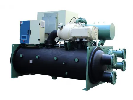 Water-Cooled Magnetic Bearing Chiller
-
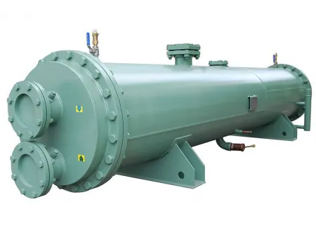 Shell and Tube Falling Film Evaporator
-
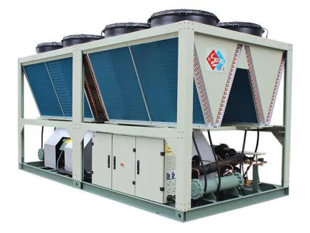 Low Temperature Air Source Heat Pump
-
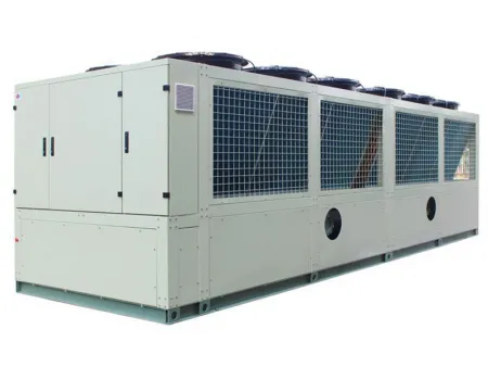 Air-Cooled Magnetic Bearing Chiller
-
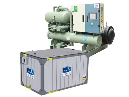 Ice Thermal Storage Chiller
-
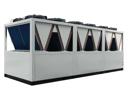 Air Source Screw Heat Pump / Hot Water Unit
-
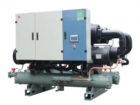 Water-Cooled Screw Chiller
-
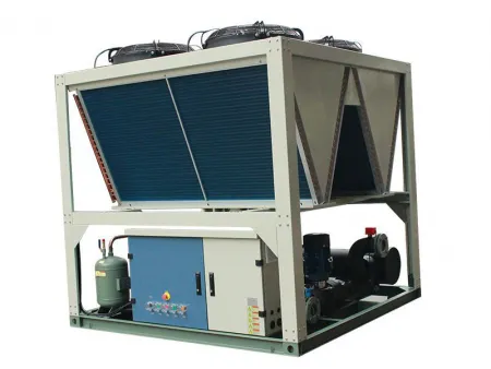 Air-Cooled Screw Chiller
-
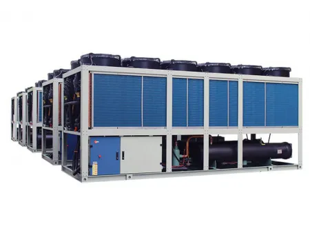 Modular Air Cooled Heat Pump
-
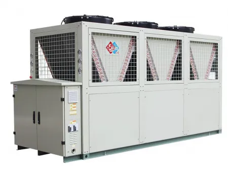 Air-Cooled Scroll Chiller
-
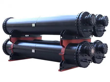 Shell and Tube Dry Expansion Evaporator
-
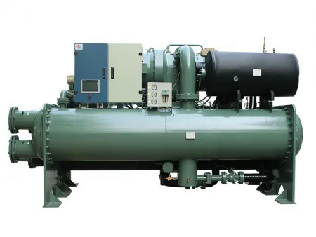 Water-Cooled Centrifugal Chiller
