Leaching Tank
Leaching Tank
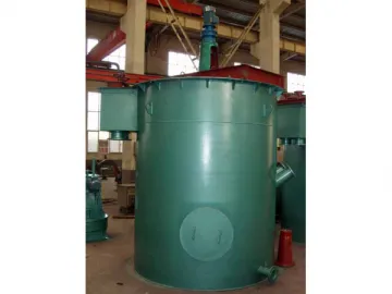
The leaching tank is designed with dual-layeredimpellers, and features rational and compact structure and high efficiency. Itslarge diameter impellers come with low rotational speed, which contributes tolow energy consumption. It is designed with a hollow shaft to suck air into thetank, and the air is mixed with ore slurry uniformly to ensure satisfyingleaching results.
Medium stirring intensity makes sure the ore slurry in the leaching tank hasuniform density and the particles in the slurry have uniform size. This canimprove the processing efficiency of the equipment. The leaching tank isextensively used for extracting valuable material such as gold and silver fromore.
Working Process
The leaching tank is equipped with an electric motor to drive the mainshaft through a reducer. The shaft then allows the impellers to rotateclockwise, which enables the ore slurry in the tank to flow in axial and radialdirections. This, coupled with continuous air supply via the hollow shaft, makessure the bubbles generated during the stirring process are fine and tinny. Ore minerals will suspendon the bubbles uniformly and can be collected finally.
Technical Parameters of the LeachingTank
| Model | Tank Size (mm) | Tank Capacity (m3) | Impeller Diameter (mm) | Impeller Speed (r/min) | Power (kw) | Weight (kg) |
| SJ-2025 | Φ2000x2500 | 6 | 900 | 52 | 2.2 | 2100 |
| SJ-2531 | Φ2500x3150 | 13.14 | 935 | 52 | 2.2 | 3100 |
| SJ-3030 | Φ3000x3000 | 18 | 1130 | 41 | 4 | 4150 |
| SJ-3035 | Φ3000x3500 | 21 | 1130 | 43 | 4 | 4400 |
| SJ-3535 | Φ3500x3500 | 30 | 1310 | 52 | 5.5 | 4900 |
| SJ-3540 | Φ3500x4000 | 32.7 | 1310 | 52 | 5.5 | 5200 |
Links:https://globefindpro.com/products/90818.html
-
 ESYS-1012 Small Music Box for Toy
-
 ESYS-6010 Customized Sound Greeting Card
-
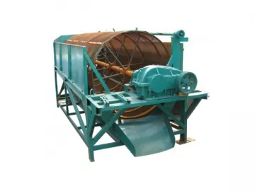 Trommel Screen
-
 ESYS-1010 Reminder Sound Box
-
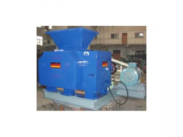 Hydraulic Briquette Machine
-
 ESYS-4006 Music and Dancing Lion Module /Talking Toys
-
 ESYS-4005 Dancing Music Module for Toy /Music Toys
-
 ESYS-2002 Cards Sound Chip
-
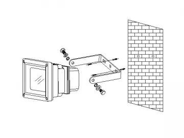 10W LED Flood Light
-
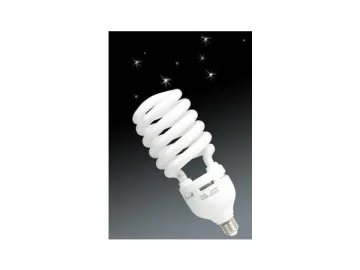 Half Spiral Energy Saving Lamp
-
 ESYS-1026 Education Music Panel
-
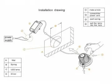 5W LED Ceiling Light Fixture
