Description
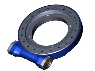
If you need slewing drive with strong scuffing resistance for harsh working conditions in the wild, our WE series horizontally mounted worm drive is a good choice. It is similar to SE series but differs in that it adopts the slewing ring with arc tooth surface. Hence, the worm drive has stronger scuffing resistance and its output torque is increased accordingly. With more superior running stability, this series of industrial gearbox is able to resist wind and sand and is suitable for use in the wild.
Advantages
1. Independently developed by our company, this worm drive adopts an enclosed structure and arc worm wheel tooth surface, so it has better rigidity and stronger impact resistance.
2. The structure design of arc tooth surface with straight worm ensures large contact area and stronger scuffing resistance.
3. To facilitate use and maintenance, our worm gearing is designed with a universal installation structure, which has strong interchangeability.
4. The input hole form makes the worm gear unit easy to connect various gear or hydraulic motors with the slewing drive.
5. Our worm drive has been recognized by customers in the Europe and Americas.
Supply Capacity
We are able to provide customization service for all of our products.
Application
The WE series horizontally mounted worm drive is widely used in the relative rotating parts of various machines.
1. Rotation in the chassis of aerial vehicle
2. Rotation of ship crane
3. Drive the arm of excavator to rotate
| Model | Output Torque | Overturning Moment | Holding Torque | Axial Static Load | Radial Static Load | Axial Dynamic Load | Radial Dynamic Load | Gear Ratio | Tracking Precision | Weight |
| WE9 | 8 kN•m | 33.9 kN•m | 38.7 kN•m | 550 kN | 205 kN | 130 kN | 110 kN | 62 : 1 | ≤ 0.15° | 48.5kg |
| 5904 lbf•ft | 25×10^3 lbf•ft | 29×10^3 lbf•ft | 123.9×10^3 lbf | 46.2×10^3 lbf | 29.3×10^3 lbf | 24.8×10^3 lbf |
| Model | Output Torque | Overturning Moment | Holding Torque | Axial Static Load | Radial Static Load | Axial Dynamic Load | Radial Dynamic Load | Gear Ratio | Tracking Precision | Weight |
| WE12 | 9.5 kN•m | 54.3 kN•m | 43 kN•m | 725 kN | 270 kN | 180 kN | 140 kN | 79 : 1 | ≤ 0.15° | 61kg |
| 7011 lbf•ft | 40×10^3 lbf•ft | 32×10^3 lbf•ft | 163×10^3 lbf | 60.8×10^3 lbf | 40.5×10^3 lbf | 31.5×10^3 lbf |
| Model | Output Torque | Overturning Moment | Holding Torque | Axial Static Load | Radial Static Load | Axial Dynamic Load | Radial Dynamic Load | Gear Ratio | Tracking Precision | Weight |
| WE14 | 10.8 kN•m | 67.8 kN•m | 48 kN•m | 920 kN | 343 kN | 220 kN | 190 kN | 86 : 1 | ≤ 0.13° | 68kg |
| 7970 lbf•ft | 50×10^3 lbf•ft | 35×10^3 lbf•ft | 207×10^3 lbf | 77.2×10^3 lbf | 49.5×10^3 lbf | 42.8×10^3 lbf |
| Model | Output Torque | Overturning Moment | Holding Torque | Axial Static Load | Radial Static Load | Axial Dynamic Load | Radial Dynamic Load | Gear Ratio | Tracking Precision | Weight |
| WE17 | 12.96 kN•m | 135.6 kN•m | 72.3 kN•m | 1110 kN | 414 kN | 266 kN | 220 kN | 104 : 1 | ≤ 0.1° | 90kg |
| 9564 lbf•ft | 100×10^3 lbf•ft | 53.4×10^3 lbf•ft | 250×10^3 lbf | 93.2×10^3 lbf | 59.9×10^3 lbf | 49.5×10^3 lbf |
| Model | Output Torque | Overturning Moment | Holding Torque | Axial Static Load | Radial Static Load | Axial Dynamic Load | Radial Dynamic Load | Gear Ratio | Tracking Precision | Weight |
| WE21 | 28.7 kN•m | 203 kN•m | 105.8 kN•m | 1598 kN | 596 kN | 340 kN | 270 kN | 90 : 1 | ≤ 0.1° | 169kg |
| 21180 lbf•ft | 150×10^3 lbf•ft | 78.1×10^3 lbf•ft | 359×10^3 lbf | 134×10^3 lbf | 76.4×10^3 lbf | 60.7×10^3 lbf |
| Model | Output Torque | Overturning Moment | Holding Torque | Axial Static Load | Radial Static Load | Axial Dynamic Load | Radial Dynamic Load | Gear Ratio | Tracking Precision | Weight |
| WE25 | 34.2 kN•m | 310 kN•m | 158.3 kN•m | 1850 kN | 690 kN | 420 kN | 320 kN | 104 : 1 | ≤ 0.1° | 199kg |
| 25240 lbf•ft | 229×10^3 lbf•ft | 117×10^3 lbf•ft | 416×10^3 lbf | 155×10^3 lbf | 94.6×10^3 lbf | 72.1×10^3 lbf |
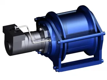 Hydraulic Winch
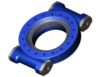 SE-2 Series Dual Worm Slewing Drive
 Doupion Silk Yarn
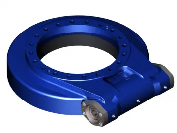 PE Series Horizontally Mounted Slewing Drive
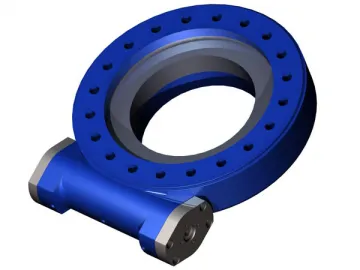 ZE Series Horizontally Mounted Slewing Drive
 Striped Silk Fabric
 Silk Satin
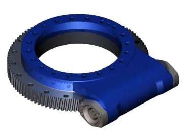 S Series Single Worm Slewing Drive
 MT Series Four Point Contact Ball Bearing
 Silk Quilts
 Thrown Silk Yarn
 Ultra-Thin X-Ray Film Viewer
