Solar Efficiency
Mean flow rate: 124 kg/h
Kind of fluid: water
Period: July 2006
1.3 Collector efficiency parameters determined
The calculated parameters rely on following areas:
aperture area of 1.706 m2: absorber area of 1.451 m2:
η0a = 0.573 η0A = 0.674
a1a = 2.085 W/m2K a1A = 2.452 W/m2K
a2a = 0.0083 W/m2K2 a2A = 0.0098 W/m2K2
Power output per collector unit [W]:
tm-ta [K] 400 [W/m2] 700 [W/m2] 1000 [W/m2]
10 354 647 941
30 272 565 858
50 178 471 764
1.4 Incidence angle modifier - IAM (measured at the outdoor test facility (tracker))
Test method: outdoor
transversal: dynamic
longitudinal: steady state
Latitude: 48.0o
Longitude: 7.8o
Collector tilt: tracked
Collector azimuth: tracked
IAM at : 0o 10o 20o 30o 40o 50o 60o 70o 73o 80o 90o
transversal: 1.00 1.00 1.02 1.10 1.22 1.37 1.42 1.27 1.42 0.93 0.05
longitudinal: 1.00 1.00 1.00 1.00 1.00 0.96 0.91 0.79 0.94 0.53 0.00
Table 1: Measured (bold) and calculated IAM data for SPA-58-1800-18-C
1.5 Effective thermal capacity of the collector
Effective thermal capacity: 25.90 kJ/K
The effective thermal capacity per sqaure meter is: 15.18 kJ/K m2
1.6 Tests on efficiency
Test Date Result
Date of delivery: 04.05.2006
Determination of
collector parameters July 2006 passed
Determination of IAM July 2006 passed
Effective thermal capacity calculated performed
1.7 Summary statement
No problems or distinctive observations occured during the measurements.
2 Test Center
Test Center for Thermal Solar Systems of Fraunhofer ISE
Heidenhofstrae 2, D-79110 Freiburg
Tel.: 49-761-4588-5354 or -5141; Fax.: 49-761-4588-9354
E-mail: arim.schaefer@ise.fraunhofer.de; rommel@ise.fraunhofer.de
Internet: http://www.kollektortest.de
3 Orderer,Expeller, Manufacturer
Orderer Sunpower Solar Water Heater Co.,Ltd
69 South Airport Road Luoxi Town Changzhou
Tel: 0086 519 508 3 201
Fax: 0086 519 508 3 220
Expeller and Manufacturer: see orderer
4 Description of the Collector
4.1 Collector
(MS) = Manufacturer Specification
Type: vacuum tube collector with heat
pipe conception
Brand name: SPA-58-1800-18-C
Serial no.: 1-180-18-0001
Year of production: 2006
Number of test collectors: 1
Collector reference no.: 2 KT 54 002 052006
Total area: 2.100 m × 1.487 m = 3.123 m2
(total dimensions without fittings)
Aperture area: 1.706 m2
(projected area of the inner diameter
of the cover tube)
Absorber area: 1.451 m2 (MS)
(projected area of outer diameter of
absorber tubes)
Material of the cover tube: Borosilcat glass (MS)
Transmission of the cover tube: n/a (MS)
Outer diameter of the cover tube: 58 mm (MS)
Thickness of the cover tube: 1.5 mm (MS)
Outer diameter of the inner tube 47 mm (MS)
Thickness of the inner tube: 1.5 mm (MS)
Length of the tubes: 1775 mm (MS)
Distance from tube to tube: 80 mm (MS)
Number of tubes: 18 (MS)
Weight empty: 58 kg (MS)
Volume of the fluid: 1.1 l (MS)
Heat transfer fluid: antifreeze persistent to high temperatures (MS)
4.2 Absorber
Material of the absorber: n/a (MS)
Kind/Brand of selective coating: sputtered (MS)
Absorptivity coefficient : 93% (MS)
Emissivity coefficient ": > 6.5 % (MS)
Material of the absorber pipes: copper (MS)
Layout of the absorber pipes: parallel, heat pipes (MS)
Number of absorber pipes: 18 (MS)
Outer diameter: 8 mm (MS)
Inner diameter: 6.8 mm (MS)
Distance between the pipes: 80 mm (MS)
Material of the header pipe: copper (MS)
Outer diameter of the header pipe: 22 mm (MS)
Inner diameter of the header pipe: 1 mm (MS)
Material of the contact sheets: aluminum (MS)
Thickness of the contact sheets: 0.2 mm (MS)
4.3 Insulation and Casing
Collector dimensions
Height, width, depth: 2.100 m; 1.487 m; 1.560 m
Medium between the inner and
outer tubes of the vacuum flask: =<3× 10⁻² Pa (MS)
Material of the casing: high-grade steel (MS)
Sealing material: silicon (MS)
4.4 Limitations
Maximum pressure: 800 kPa (MS)
Operating pressure: 6 bar (MS)
Maximum service temperature: 125oC
Maximum stagnation temperature: 250oC
Flow range recommendation: 1.1 l/m2h (MS)
4.5 Kind of mounting
Flat roof, mounted on the roof: yes (MS)
Tilted roof, mounted on the roof: yes (MS)
Tilted roof, integrated: no (MS)
Free mounting: yes (MS)
Fassade: yes (MS)
4.6 Picture and cut drawing of the collector
Figure 1: Picture of the collector SPA-58-1800-18-C mounted on the test facility of Fraunhofer ISE
Figure 2: Cut drawing of the vacuum tube KTB Nr.
5 Collector efficiency parameters
5.1 Test method
Outdoor, steady state according to EN 12975-2:2006
Thermal solar systems and components, solar collectors, test methods
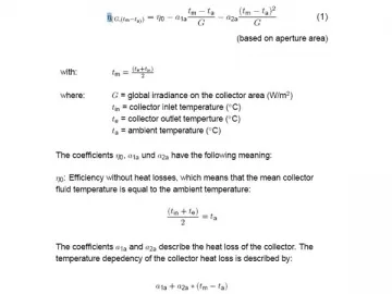
5.2 Description of the calculation
The functional dependence of the collector efficiency on the meteorological
and system operation values can be represented by the following
mathematical equation:
5.3 Instantaneous efficiency parameters based on aperture and absorber area and
mean temperature of heat transfer fluid
Boundary conditions:
Test method: outdoor, steady state
Latitude: 48.0o
Longitude: 7.8o
Collector tilt: tracked between 40oand 50o
Collector azimuth: tracked
Test conditions:
Mean irradiation : 986 W/m2
Mean wind speed: 3 m/s
Mean flow rate: 124 kg/h
Kind of fluid: water
Results:
The calculated parameters rely on following areas1:
aperture area absorber area
(1.706 m2): (1.451 m2):
The determination for the standard deviation (k=2) was performed
according ENV 13025 (GUM). Based on this calculation the uncertainty is
less than 2%-points of the efficiency values over the complete measured
temperature range (η0a = 0.573 /- 0.02). Based on our experience with
the test facilities the uncertainty is much smaller and in a range of
/- 1%-point. The standard deviation of the heat loss parameters resulting
from the regression fit curve through the measurements points is:
a1a = 2.085 /- 0.087 and
a2a = 0.0083 /- 0.0012 .
1absorber area - projected area of absorber tube,
aperture area - projected area of inner diameter of cover tube
6 Incidence angle modifier IAM
The incidence angle modifier IAM is a correction factor representing how
the angel of radiation affects the performance of a collector. The IAM is
described by a longitudinal and a transversal component.
IAM longitudinal:
The tilt angle of the collector in combination with the zenith angle of the sun
results in the incident angle theta (=Θ) in longitudinal direction.
IAM transversal:
The orientation angle of the collector in combination with the azimuth angle
of the sun results in the incident angle theta (=Θ) in transversal direction.
The transversal measurement was performed dynamically, what means
that the orientation of the tracker was fixed, just the tilt angle was tracked.
So the sun is turning around the collector and there is no longitudinal
influence (transversal at the present collector means transversal to the
ligament of the cover). The incident angle is changing during the day. The
resulting values for the incident angle Θ are the mean values between the
east and the west measurement.
For the measurement of the IAM longitudinal the orientation and the tilt
angle of the tracker were tracked, which means a steady state
measurement.
Test method: outdoor
transversal: dynamic
longitudinal: steady state
Latitude: 48.0o
Longitude: 7.8o
Collector tilt: tracked
Collector azimuth: tracked
IAM at : 0o 10o 20o 30o 40o 50o 60o 70o 73o 80o 90o
transversal: 1.00 1.00 1.02 1.10 1.22 1.37 1.42 1.27 1.42 0.93 0.05
longitudinal: 1.00 1.00 1.00 1.00 1.00 0.96 0.91 0.79 0.94 0.53 0.00
Table 2: Measured (bold) and calculated IAM data for SPA-58-1800-18-C
The IAM longitudinal was measured for one angle = 50
. All other angles
for the IAM longitudinal in table 2 were calculated according to Ambrosetti
1(equation 2).
7 Effective thermal capacity of the collector
The effective thermal capacity of the collector is calculated according to
section 6.1.6.2 of EN 12975-2: 25.90 kJ/K
The effective thermal capacity per square meter is: 15.18 kJ/K m2
9 Collector identification
The collector identification/documentation according EN 12975-1 chapter 7
was complete, see the following items:
Drawings and data sheet
Labeling of the collector
Installer instruction manual
List of used materials
10 Summary statement
The measurements were carried out in July 2006.
No problems or distinctive observations occurred during the measurements.
11 Annotation to the test report
The results described in this test report refer only to the test collector. It is
not allowed to make extract copies of this test report.
Test report: KTB Nr. 2006-12-a-en-k
Freiburg, 17th August 2006
Fraunhofer-Institute for Solar Energy Systems ISE
B Efficiency curve and measured data
B.1 Efficiency curve with measurement points based on aperture area 1.706 m2
Figure 6: Efficiency curve scaled to 800 W/m2 based on aperture area 1.706 m2
The calculated parameters rely on following areas:
aperture area: absorber area:
a0.05a = 0.452 0.05A = 0.532
a0.05 is the efficiency of the collector for following conditions (for example):
an irradiation of 800 W/m2, an ambient temperature of 20oC and a mean
collector temperature of 60oC. These are typical conditions for solar
domestic hot water systems.
B.3 Measured data for efficiency curve
Links:https://globefindpro.com/products/87767.html
-
 Trailer Diesel Generator Set
-
 Solar Photovoltaic Project
-
 Automatic Transfer Switch
-
 15kVA Silent Diesel Generator Set
-
 Ⅵ Type Flat Plate Solar Energy Collector
-
 Villa Split Solar Water Heating System
-
 Civil Energy Saving Project
-
 Geothermal Heat Pump Project
-
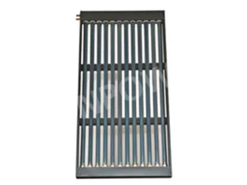 U-pipe Solar Energy Collector
-
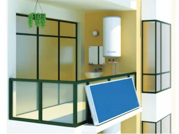 Balcony Wall Mount Solar Water Heating System
-
 Ⅱ Type Flat Panel Solar Collector
-
 Ⅳ Type Flat Plate Solar Energy Collector
