Polymer Line Post Insulator
Launched in 2011, the polymer line post insulator is horizontally mounted and mainly used in high voltage lines. It has been exported to Africa and South America. Custom-made products can be made according to the technical parameters or drawings provided by the customers.
2.5" (63mm) Core, Standard Leakage Shed (SN) Series Line Post Insulator
| Typical System VoltagekV | Catalog No. | No. of Sheds | Section LengthIn (mm) | Dry Arcing DistanceIn (mm) | Leakage DistanceIn (mm) | Low Frequency Flashover | Critical Impulse Flashover | Maximum Design Cantilever LoadLbs. (kN) | Approx. WeightLbs. (kg) | ||
| Dry kV | Wet kV | Pos. kV | Neg. kV | ||||||||
| 69 | RLP4-SN141-DBF | 14 | 32.1 (816) | 22.3 (567.5) | 57.9 (1470) | 265 | 230 | 370 | 425 | 2860 (12.7) | 51.3 (23.3) |
| 69/110 | RLP4-SN181-DBF | 18 | 37.9 (963) | 28.2 (717.5) | 74.4 (1890) | 325 | 285 | 460 | 515 | 2395 (10.6) | 54.9 (24.9) |
| 69/110 | RLP4-SN211-DBF | 21 | 42.2 (1073) | 32.7 (830.0) | 86.8 (2205) | 370 | 325 | 525 | 585 | 2160 (9.6) | 57.6 (26.1) |
| 110 | RLP4-SN251-DBF | 25 | 48.0 (1220) | 38.6 (980.0) | 103.3 (2625) | 425 | 370 | 615 | 675 | 1910 (8.5) | 61.2 (27.8) |
| 110/132 | RLP4-SN291-DBF | 29 | 53.8 (1366) | 44.5 (1130.0) | 119.9 (3045) | 475 | 420 | 700 | 770 | 1670 (7.4) | 64.8 (29.4) |
| 110/132 | RLP4-SN321-DBF | 32 | 58.1 (1476) | 48.9 (1242.5) | 132.3 (3360) | 515 | 450 | 765 | 840 | 1530 (6.8) | 67.5 (30.7) |
| 132 | RLP4-SN361-DBF | 36 | 63.9 (1623) | 54.8 (1392.5) | 148.8 (3780) | 565 | 495 | 855 | 930 | 1375 (6.1) | 71.2 (32.3) |
| 161 | RLP4-SN391-DBF | 39 | 68.2 (1733) | 59.3 (1505.0) | 161.2 (4095) | 600 | 525 | 920 | 1000 | 1275 (5.7) | 73.9 (33.5) |
| 161 | RLP4-SN431-DBF | 43 | 74.0 (1880) | 65.2 (1655.0) | 177.8 (4515) | 645 | 565 | 1010 | 1090 | 1165 (5.2) | 77.5 (35.2) |
| 220 | RLP4-SN471-DBF | 47 | 79.8 (2027) | 71.1 (1805.0) | 194.3 (4935) | 690 | 605 | 1095 | 1180 | 1075 (4.8) | 81.1 (36.8) |
| 220 | RLP4-SN511-DBF | 51 | 85.6 (2173) | 77.0 (1995.0) | 210.8 (5335) | 730 | 640 | 1185 | 1275 | 995 (4.4) | 84.7 (38.5) |
| 230 | RLP4-SN551-DBF | 55 | 91.3 (2320) | 82.9 (2105.0) | 227.4 (5775) | 770 | 675 | 1270 | 1365 | 925 (4.1) | 88.3 (40.1) |
| 230 | RLP4-SN581-DBF | 58 | 95.7 (2430) | 87.3 (2217.5) | 239.8 (6090) | 800 | 700 | 1340 | 1435 | 880 (3.9) | 91.1 (41.3) |
Notes
1. The specified mechanical load and minimum routine test load for the drop tongue are 15,000 lbs and 7500 lbs respectively. They are 5000 lbs and 2500 lbs respectively for the clamp top.
2. The standard line fittings and base fittings available are listed below. For other special base end fittings, please contact us.
Line fittings: D – Drop Tongue or Two Hole Blade, H – Horizontal Clamp Top, V – Vertical Clamp Top, F – F-Neck, C – Clevis
Base fittings: CB – Bolt Circle Base, BC – Bendable Curved Base, BF – Bendable Flat Base, SB – 3/4" or 7/8" Stud Base, GB – Gain Base, RC – Rigid Curved Base, RF – Rigid Flat Base
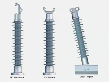
Polymer Line Post Insulator
| Typical System Voltage(kV) | Catalog No. | Section Length(mm) | Dry Arcing DistanceInch (mm) | Leakage Distance(mm) | 60Hz Lower Frequency Flashover | Critical Impulse Flashover (kV) | SCL Pounds(kN) | Max. Design Cantilever LoadPounds (KN) | Approx. WeightPounds (kg) | ||
| DrykV | WetkV | Pos.kV | Neg.kV | ||||||||
| 15 | RLP1-15-HGB | 318 | 7.3 (184) | 14.4 (364) | 90 | 70 | 150 | 140 | 2800 (12.5) | 1235 (5.5) | 9.8 (4.5) |
| RLP1-15-HSB | 340 | 6.9 (3.1) | |||||||||
| RLP1-15-VSB | 324 | 6.5 (2.9) | |||||||||
| RLP1-15-FSB | 315 | 6.6 (3.0) | |||||||||
| 28 | RLP1-28-HGB | 370 | 9.9 (250) | 23.3 (592) | 115 | 80 | 190 | 175 | 2800 (12.5) | 1235 (5.5) | 10.3 (4.7) |
| RLP1-28-HSB | 390 | 7.3 (3.3) | |||||||||
| RLP1-28-VSB | 375 | 7.0 (3.2) | |||||||||
| RLP1-28-FSB | 368 | 7.1 (3.2) | |||||||||
| 35 | RLP1-35-HGB | 442 | 12.5 (316) | 32.3 (820) | 145 | 115 | 225 | 210 | 2800 (12.5) | 1235 (5.5) | 11.2 (5.1) |
| RLP1-35-HSB | 462 | 8.2 (3.7) | |||||||||
| RLP1-35-VSB | 448 | 7.8 (3.5) | |||||||||
| RLP1-35-FSB | 440 | 8.0 (3.6) | |||||||||
| 46 | RLP2-46-DGB | 498 | 15.4 (390) | 42.2 (1071) | 170 | 140 | 260 | 340 | 3150 (14.0) | 1580 (7.0) | 21.6 (9.8) |
| RLP2-46-DSB | 520 | 16.5 (7.5) | |||||||||
| RLP2-46-HGB | 544 | 20.4 (9.3) | |||||||||
| RLP2-46-HSB | 552 | 15.7 (7.1) | |||||||||
| RLP2-46-VSB | 540 | 16.3 (7.4) | |||||||||
| RLP2-46-FSB | 525 | 15.9 (7.2) | |||||||||
| 69 | RLP2-69-DGB | 678 | 22.4 (570) | 64.8 (1647) | 245 | 195 | 370 | 340 | 2475 (11.0) | 1240 (5.5) | 24.2 (11.0) |
| RLP2-69-DSB | 700 | 19.2 (8.7) | |||||||||
| RLP2-69-HGB | 723 | 23.3 (10.6) | |||||||||
| RLP2-69-HSB | 732 | 18.5 (8.4) | |||||||||
| RLP2-69-VSB | 720 | 18.9 (8.6) | |||||||||
| RLP2-69-FSB | 705 | 14.08 (6.4) | |||||||||
| 72 | RLP2-72-DGB | 738 | 24.8 (630) | 72.4 (1839) | 270 | 230 | 400 | 450 | 2030 (9.0) | 1010 (4.5) | 25.1 (11.4) |
| RLP2-72-DSB | 760 | 19.8 (9.0) | |||||||||
| RLP2-72-HGB | 783 | 24.2 (11.0) | |||||||||
| RLP2-72-HSB | 792 | 19.5 (8.8) | |||||||||
| RLP2-72-VSB | 780 | 19.6 (8.9) | |||||||||
| RLP2-72-FSB | 765 | 19.4 (8.8) | |||||||||
| 69 | RLP3-69-HGB | 805 | 28.9 (710) | 96.1 (2440) | 325 | 285 | 460 | 515 | 5720 (23.4) | 2860 (11.7) | 22.0 (10.0) |
Notes:
1. Maximum design tension for clamp top is 2500 pounds or 11kN.
2. RLP1 series of products use the rod with the diameter of 1.5 inch or 38mm.
3. RLP2 series of products use the rod with the diameter of 1.75 inch or 44mm.
4. RLP3 series of products use the rod with the diameter of 2 inch or 50mm.
Other Picture
Related Names
Horizontal Mounted Insulator | Strain Insulator | High Voltage Insulator
Links:https://globefindpro.com/products/81907.html
-
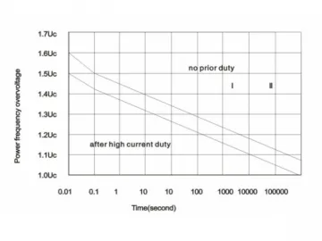 Zinc-Oxide Varistor
-
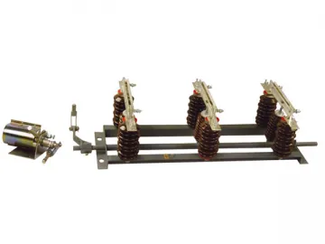 (H)GW1 Outdoor High Voltage AC Disconnector
-
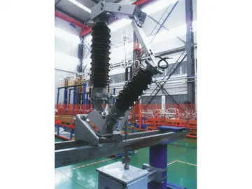 GW13 Outdoor High Voltage AC Neutral Point Disconnector
-
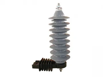 Y5C, Y10C Series Porcelain Lightning Arrester
-
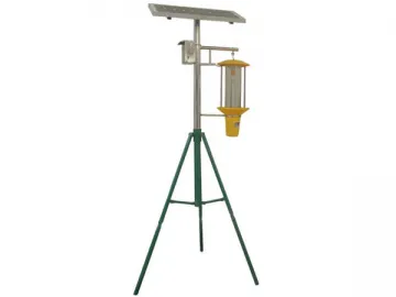 Solar Bug Zapper (Portable Style)
-
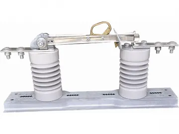 (H)GW9 Outdoor High Voltage AC Disconnector
-
 Electric Fly Killer
-
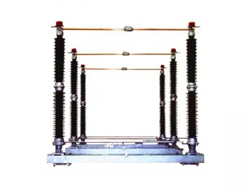 GW4 – 252(D)(W) Outdoor High Voltage Disconnector
-
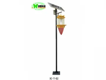 Solar Bug Zapper (Post Style)
-
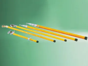 Fuse Cutout Accessories
-
 Standard Moth Traps
-
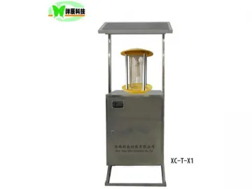 Solar Bug Zapper (Box Style)
