Magnetic Separator
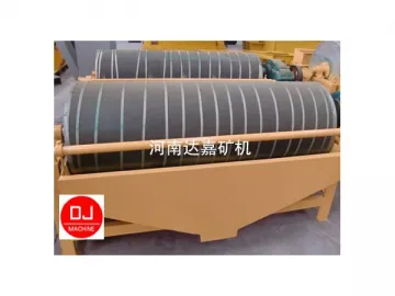
This series of magnetic separator is characterized by its intensive magnetic field, great separation factor, optimized structure, light weight, dependable operating efficiency, and convenient maintenance. It is well suited for use in areas facing severe water shortage where precocious water must be saved and ore dressing cost needs to be reduced. Over history, industry has developed a variety of new ways to carry out ore dressing. One way is to utilize the magnetic field. At remotely located mine site where electricity is often not available, our separator can be used, as it can be driven by a diesel engine. The magnetic field strength it produces may vary according to the variety of minerals to be separated.
Application
Automatic separation/recovery of ferrous and non-ferrous materials
Work Principle
The mineral slurry flows into the drum via the feed hopper. The impact force of water flow causes the tightly bonded mineral particles to become loose. The water flow is created by a pump that is attached to the drum. There are magnetic poles installed around the circumference of the drum inner wall, evenly spaced apart with alternating negative and positive polarity.
Under the influence of magnetic field, magnetically susceptible particles swarm together to form magnetic chain or magnetic cluster. Attracted by the magnetic field, the magnetic cluster swims towards and clings to the surface of the magnetic pole. The rotation of the drum causes the magnetic filed to reverse its polarity alternately, which in turn enables the magnetic chain to spin very quickly and stir the mineral slurry. As the mixture is tumbled within the drum, gangues and other non-magnetic ores contained in the magnetic cluster come off of it. The result of this tumbling process is that the magnetic cluster which clings to the surface of the drum gets purified. The cluster usually sticks to the end of a magnetic pole where the magnetic strength is the weakest. Operators can use a water pipe to flush the cluster off the pole and discharge it into a trough. Non-magnetic ores are discharged from the opening at the base of drum. They are called tailings.
| Model | Magnetic Field Intensity (Oe ) | Production Capacity (t/h) | Power (kw ) | Weight (kg) |
| CTB600×1200 | 1450 | 8-15 | 1.5 | 910 |
| CTB600×1800 | 1500 | 15-25 | 2.2 | 1340 |
| CTB750×1800 | 1550 | 30-45 | 3 | 2050 |
| CTB900×1800 | 1650 | 35-60 | 4 | 3000 |
| CTB1050×2400 | 1650 | 60-95 | 5.5 | 5020 |
| CTB1200×3000 | 1650 | 80-150 | 7.5 | 7800 |
| CTB1500×3000 | 1650 | 120-200 | 11 | 9600 |
| Basic Parameters | Model | |||||
| GYC-60B | GYC-60B-I | GYC-2×60 | GYC-3×60 | GYC-3×80 | GYC-4×80 | |
| Drum Diameter × Length (mm) | Φ320×600 | Φ320×600 | Φ320×600 | Φ320×600 | Φ404×800 | Φ404×800 |
| Max. Magnetic Induction Intensity | 3500 | 1100 | 3500 | 110-3000-3500 | 110-3000-3500 | 110-3000-5000 |
| Quantities of Drum | 1 | 1 | 2 | 3 | 3 | 4 |
| Rotating Speed of Drum (r/min) | 66.47.33 | 66.47.33 | 66.47.33 | 34.5-172 (adjustable) | 54.5-172 (adjustable) | 54.5-172 (adjustable) |
| Dimensions of Raw Materials (mm) | 0.05-25 | 0.063-25 | 0.05-25 | 0-8 | 0-8 | 0-8 |
| Motor Model | Y801-4 | Y801-4 | Y801-4 | ZBW-1.5 | ZBW-1.5 | ZBW-1.5 |
| Power (kw) | 0.75 | 0.75 | 0.75 | 1.1 | 1.5 | 2.2 |
| Productivity t /h | 0.5-2.5 | 0.1-3 | 0.5-2.5 | 0.8-2.5 | 1.5-2.5 | 1.5-2.5 |
| Weight | 0.25 | 0.65 | 0.5 | 1.2 | 1.5 | 2.4 |
| Application and Description | Fine selection | Coarse selection | Fine selection | With vibrating feeder | With vibrating feeder | Fine selection |
Related Names
Solid Mineral Separator | Iron Ore Separator | Metal Separation Equipment
Links:https://globefindpro.com/products/85401.html
