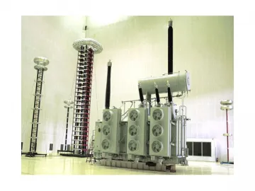
765kV Ultra High Voltage Transformer
The ODFPS-500000/750GY 765kV ultra high voltage transformer is a product independently developed by our company with the largest capacity and highest voltage level. According to the technical requirements and by summarizing years of experience in the design of 500kV transformer and analyzing technical information of EHV transformer at home and abroad, we finally decided to adopt the single-phase, four-column structure whose jamb is equipped with voltage regulating devices. Features of each part are as follows.
1. The single-phase four-column MO type iron core is adopted. The cross section of the iron core is reasonably optimized. High-quality silicone steel sheet with high magnetic permeability is adopted as the iron core sheet. Multiple sheets are connected with miter joints, which ensures good no-load performance but requires high machining precision. Two iron core sheets are piled up and they are not stacked on the upper yoke. This can greatly reduce excitation current and no-load loss. The iron core column and iron yoke are bundled with the epoxy weftless glass fiber adhesive tape, which is safe and reliable. The iron core and clamps are completely insulated, and they are respectively drawn forth and grounded through the ground sleeve on the fuel tank, avoiding inter-turn short circuit.
2. Internally shielded continuous coil is adopted and transposed conductors are used. The coil is set with axial and transverse oil passages to ensure good heat dissipation of the windings and reduce temperature rise of the coil. The two columns with high voltage winding and low voltage winding are connected in series, and the two columns with medium voltage windings are connected in parallel. This can reduce the transport dimensions of the transformer.
The winding adopts high quality low resistivity oxygen-free copper. The high voltage winding is tangle type plus inserted shielded continuous type. This structure can improve the potential gradient distribution of the line ends under impulse voltage. The medium voltage winding is inserted shielded continuous type and the low voltage winding is single spiral type. The ampere-turn distribution is optimized and the winding radial supporting force and axial compression force are increased. Adopting overall packaging, constant voltage drying, and other technologies, the windings enjoy strong impact current resistance.
3. Major insulation of the coil adopts a thin paper tube small oil clearance structure. In this structure, the thickness of the paper tube is less than 4 mm and the width of oil clearance is less than 15 mm. Electrostatic rings are placed at the ends of the windings, which can improve the impulse voltage distribution of adjacent segments and make the electric field at the coil ends even. An oil cylinder pressure screw device is used for compaction, which can not only ensure continuous pressure against the windings but also prevent the transformer from being damaged by the electrodynamic force produced by the windings at short circuit. The top fastening device between the transformer body and the oil cylinder as well as the positioning device of the transformer has gone through special treatment, making the body completely insulated from the oil cylinder, thus preventing inter-turn short circuit.
4. The high voltage winding adopts a two-columns-in-series structure with wire outgoing in the center. The insulating member from WEIDMANN is used for insulation of outgoing line, which can guarantee the quality of line outgoing.
5. The top fuel tank has a bell-type structure and the bottom fuel tank has a box type structure. The oil cylinder is designed with copper shield and magnetic shielding, which can effectively shield the leakage flux entering the tank, reduce stray losses, and prevent local overheating.
Related Names
Substation Transformer | Electric Power Transformer | Extra High Tension Transformer
Links:https://globefindpro.com/products/85246.html
-
 TKDM1L Residual Current Operated Circuit Breaker
-
 Reactor
-
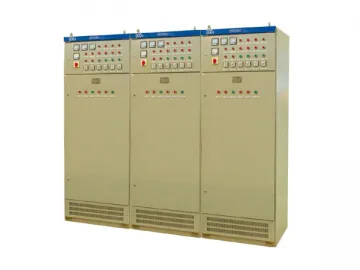 GGD AC Low Voltage Distribution Switchgear
-
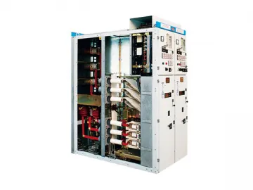 Fixed AC Metal-enclosed Switchgear
-
 Seamless Reflective Vinyl Banner Material
-
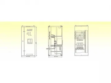 MNS-II Drawout Low Voltage Switchgear
-
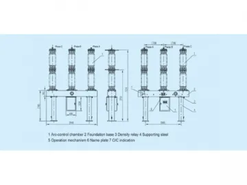 72.5~252kV SF6 Circuit Breaker
-
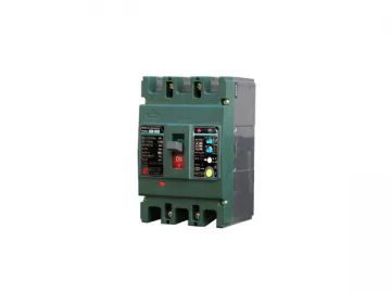 TKDM1 Molded Case Circuit Breaker
-
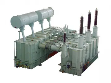 10~220kV Rectifier Transformer
-
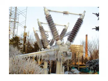 GW5 High Voltage Disconnector
-
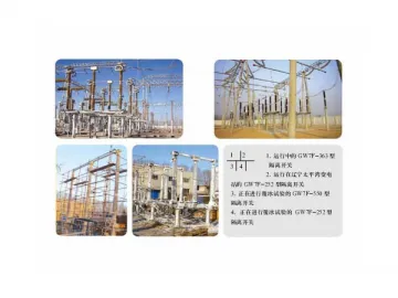 GW7F High Voltage Disconnector
-
 AC Metal Oxide Lightning Arrester
