GW5 High Voltage Disconnector
1. Product Overview
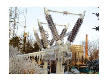
a. The GW5 high voltage disconnector is applicable to switching of high voltage lines with no load. It is also used for isolating high voltage busbar and electrical equipment like circuit breaker from the live high voltage lines when the busbar and electrical equipment need maintenance.
b. Our GW5 AC disconnector consists of the base, post insulators, and the conducting parts. It includes three monopoles and each monopole has a V type double-column structure. The two post insulators of each monopole are arranged in an angle of 50 degrees and they are mounted on the bearing seats connected with the base. A pair of bevel gears is adopted for meshing transmission. The knife switch has left and right contacts which are respectively fixed on the post insulators.
c. The activated operating mechanism drives one post insulator to rotate by 90° and the other insulator rotates by 90° in the opposite direction at the same time due to the meshing between the bevel gears. Hence, the left and right contacts are opened or closed to the same side. During opening, there is a clearly noticeable horizontal isolation fracture between the two contacts.
d. The GW5 high voltage disconnector can be equipped with a JW7 earthing switch. A mechanical interlock is set between the two.
e. Three-pole mechanical linkage can be realized through the connecting rods between the monopoles. Both the main switch and the earthing switch can be equipped with the CS17I to CS17IV series of improved manual operating mechanisms. The CJTKB electric mechanism can also be adopted according to customer requirements.
2. Product Classification
a. Divided by voltage level: 40.5kV, 72.5 kV, 126 kV, 145 kV;
b. Divided by current level: 630A,1250A, 1600A, 2000A,2500A,3150A;
c. Divided by whether there is a grounding switch: Not grounded, left grounded, right grounded, double grounded;
d. Divided by transmission mode: 90-degree transmission, 180-degree transmission
Table 1
| Model | GW5-40.5Ⅲ | GW5-72.5Ⅲ | |||||||||||
| Rated voltage kV | 40.5 | 72.5 | |||||||||||
| Rated current A | 630 | 1250 | 1600 | 2000 | 2500 | 3150 | 630 | 1250 | 1600 | 2000 | 2500 | 3150 | |
| Isolation switch | Rated peak withstand current kA | 80, 100 | 80, 100 | 100, 125 | 100, 125 | 125 | 125 | 80, 100 | 80, 100 | 100, 125 | 100, 125 | 125 | 125 |
| Rated short-time withstand current (rms) kA | 31.5, 40 | 31.5, 40 | 40, 50 | 40, 50 | 50 | 50 | 31.5,40 | 31.5, 40 | 40, 50 | 40, 50 | 50 | 50 | |
| Rated short-circuit duration s | 4s for 31.5kA, 40kA 3s for 50kA | ||||||||||||
| Earthing switch | Rated peak withstand current kA | 100, 125 | |||||||||||
| Rated short-time withstand current (rms) kA | 40, 50 | ||||||||||||
| Rated short-circuit duration s | 4, 3 | ||||||||||||
| Rated short-time power frequency withstand voltage (rms) kV | To earth | 95/107* | 160/181* | ||||||||||
| Between fractures | 118/134* | 200/226* | |||||||||||
| Rated lightning impulse withstand voltage (peak) kV | To earth | 185/210* | 350/396* | ||||||||||
| Between fractures | 215/243* | 410/464* | |||||||||||
| Rated terminal static mechanical load N | Horizontal longitudinal | 1000 | 1000 | ||||||||||
| Horizontal transverse | 750 | 750 | |||||||||||
| Vertical | 1000 | 1000 | |||||||||||
| Opening and closing bus switching current (bus transfer voltage: 100V)A | 504 | 1000 | 1280 | 1600 | 2000 | 2500 | 504 | 1000 | 1280 | 1600 | 2000 | 2500 | |
| Radio interference level | ≤500μV | ||||||||||||
| Capacitive current opened and closed (phase voltage) A | 1, 2 | ||||||||||||
| Inductor current opened and closed (phase voltage) A | 0.5, 1 | ||||||||||||
| Mechanical life | 3000 times | ||||||||||||
| Monopole weight kg | 150 | 190 | |||||||||||
| Model | GW5-126Ⅲ | GW5-145Ⅲ | |||||||||||
| Rated voltage kV | 126 | 145 | |||||||||||
| Rated current A | 630 | 1250 | 1600 | 2000 | 2500 | 3150 | 630 | 1250 | 1600 | 2000 | 2500 | 3150 | |
| Isolation switch | Rated peak withstand current kA | 80, 100 | 80, 100 | 100, 125 | 100, 125 | 125 | 125 | 80, 100 | 80, 100 | 100, 125 | 100, 125 | 125 | 125 |
| Rated short-time withstand current (rms) kA | 31.5, 40 | 31.5, 40 | 40, 50 | 40, 50 | 50 | 50 | 31.5, 40 | 31.5, 40 | 40, 50 | 40, 50 | 50 | 50 | |
| Rated short-circuit duration s | 4s for 31.5kA, 40kA 3s for 50kA | ||||||||||||
| Earthing switch | Rated peak withstand current kA | 100, 125 | |||||||||||
| Rated short-time withstand current (rms) kA | 40, 50 | ||||||||||||
| Rated short-circuit duration s | 4, 3 | ||||||||||||
| Rated short-time power frequency withstand voltage (rms) kV | To earth | 230/260* | 285/325* | ||||||||||
| Between fractures | 300/340* | 330/375* | |||||||||||
| Rated lightning impulse withstand voltage (peak) kV | To earth | 550/625* | 660/750* | ||||||||||
| Between fractures | 650/740* | 760/860* | |||||||||||
| Rated terminal static mechanical load N | Horizontal longitudinal | 1250 | 1500 | ||||||||||
| Horizontal transverse | 750 | 1000 | |||||||||||
| Vertical | 1000 | 1250 | |||||||||||
| Opening and closing bus switching current (bus transfer voltage: 100V) A | 504 | 1000 | 1280 | 1600 | 2000 | 2500 | 504 | 1000 | 1280 | 1600 | 2000 | 2500 | |
| Radio interference level | ≤500μV | ||||||||||||
| Capacitive current opened and closed (phase voltage) A | 1, 2 | ||||||||||||
| Inductor current opened and closed (phase voltage) A | 0.5, 1 | ||||||||||||
| Mechanical life | 3000 times | ||||||||||||
| Monopole weight kg | 240 | 350 | |||||||||||
Note: For the data marked with "*" in Table 1 and 2, the number before "/" is the parameter value at an altitude of 2000 m and the number after "/" is the parameter value at an altitude of 1000 m.
4. Service and Installation Conditions
Ambient temperature: -50℃~ 50℃;
Altitude: ≤ 2000m;
Wind pressure: ≤ 700Pa;
Ice thickness: ≤ 20 mm;
Pollution class: class III and IV;
Seismic intensity: ≤ 9 class;
There should be no inflammable, explosive, corrosive materials or severe vibration at the installation site.
Related Names
Earth Leakage Switch | Electrical Disconnect Device | High Voltage Supply Switch
Links:https://globefindpro.com/products/85242.html
-
 10~220kV Rectifier Transformer
-
 TKDM1 Molded Case Circuit Breaker
-
 72.5~252kV SF6 Circuit Breaker
-
 765kV Ultra High Voltage Transformer
-
 TKDM1L Residual Current Operated Circuit Breaker
-
 Reactor
-
 GW7F High Voltage Disconnector
-
 AC Metal Oxide Lightning Arrester
-
 GW6A High Voltage Disconnector
-
 TK-SVC(MCR) High Voltage Dynamic Var Compensator
-
 Outdoor High Voltage SF6 Dead Tank Circuit Breaker
-
 TKDW Intelligent Air Circuit Breaker
