Guillotine Shear
The hydraulic guillotine shear is provided with more than 30 models. To satisfy different requirements, the allowable sheet thickness ranges from 6mm to 40mm, and the maximum width of sheet reaches 3200mm. All welded steel structure provides good rigidity and stable performance, and has undergone heat treatment as well as a process known as vibration stress relief to eliminate internal stress.
Features of Guillotine Shear
1. The guillotine shear uses an advanced integrated hydraulic system, ensuring good stability.
2. This sheet metal guillotine uses advanced roller guide, which eliminates the gap of guide rail and improves shearing quality.
3. The operator can make a fine adjustment manually to the electric back gauge whose movement is shown on a digital display.
4. The blade gap may be rapidly and accurately adjusted through a hand wheel.
5. With long service life, the four cutting edges of its square blade all can be used. Its shear angle supports adjustment, reducing the deformation possibility of sheet metal.
6. Its top tool rest is tilted inwards, which helps to collect processed workpieces and increases working accuracy.
7. The guillotine shear realizes shearing sheets sectionally and is fitted with a lighting device.
8. The machine can be equipped with a special device to prop up the materials from the rear.
9. To meet your needs, there are various CNC control panel options.
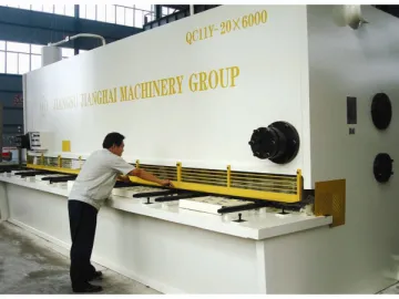
CNC Control Panel for Metal Shear
Technical Parameters
| Model | Sheet Thickness (mm) | Sheet Width (mm) | Frequency of stroke (times/min) | Back gauge range (mm) | Rake Angle (° ) | Main motor power (kw) |
| QC11Y-6×2500 | 6 | 2500 | 10 ~35 | 20~600 | 0.5° ~2.5° | 7.5 |
| QC11Y-6×3200 | 6 | 3200 | 8 ~35 | 20~600 | 0.5° ~2.5° | 7.5 |
| QC11Y-6×4000 | 6 | 4000 | 7 ~35 | 20~600 | 0.5° ~2.5° | 7.5 |
| QC11Y-6×5000 | 6 | 5000 | 6 ~25 | 20~600 | 0.5° ~2.5° | 11 |
| QC11Y-6×6000 | 6 | 6000 | 5 ~25 | 20~600 | 0.5° ~2.5° | 11 |
| QC11Y-8×2500 | 8 | 2500 | 10 ~35 | 20~600 | 0.5° ~2.5° | 11 |
| QC11Y-8×3200 | 8 | 3200 | 8 ~35 | 20~600 | 0.5° ~2.5° | 11 |
| QC11Y-8×4000 | 8 | 4000 | 7 ~35 | 20~600 | 0.5° ~2.5° | 11 |
| QC11Y-8×5000 | 8 | 5000 | 6 ~25 | 20~600 | 0.5° ~2° | 15 |
| QC11Y-8×6000 | 8 | 6000 | 5 ~25 | 20~600 | 0.5° ~2° | 15 |
| QC11Y-12×2500 | 12 | 2500 | 10 ~35 | 20~800 | 0.5° ~2.5° | 18.5 |
| QC11Y-12×3200 | 12 | 3200 | 6 ~20 | 20~800 | 0.5° ~2.5° | 18.5 |
| QC11Y-12×4000 | 12 | 4000 | 6 ~20 | 20~800 | 0.5° ~2.5° | 18.5 |
| QC11Y-12×5000 | 12 | 5000 | 5 ~15 | 20~800 | 0.5° ~2.5° | 18.5 |
| QC11Y-12×6000 | 12 | 6000 | 6 ~15 | 20~800 | 0.5° ~2.5° | 30 |
| QC11Y-16×2500 | 16 | 2500 | 8 ~30 | 20~800 | 0.5° ~3° | 22 |
| QC11Y-16×3200 | 16 | 3200 | 7 ~30 | 20~800 | 0.5° ~3° | 30 |
| QC11Y-16×4000 | 16 | 4000 | 6 ~30 | 20~800 | 0.5° ~3° | 30 |
| QC11Y-16×5000 | 16 | 5000 | 6 ~15 | 20~800 | 0.5° ~2.5° | 30 |
| QC11Y-16×6000 | 16 | 6000 | 5 ~15 | 20~800 | 0.5° ~2.5° | 37 |
| QC11Y-20×2500 | 20 | 2500 | 9 ~30 | 20~1000 | 0.5° ~3° | 30 |
| QC11Y-20×3200 | 20 | 3200 | 7 ~30 | 20~1000 | 0.5° ~3° | 30 |
| QC11Y-20×4000 | 20 | 4000 | 6 ~30 | 20~1000 | 0.5° ~3° | 30 |
| QC11Y-20×5000 | 20 | 5000 | 5 ~30 | 20~1000 | 0.5° ~2.5° | 37 |
| QC11Y-20×6000 | 20 | 6000 | 5 ~15 | 20~1000 | 0.5° ~2.5° | 45 |
| QC11Y-25×2500 | 25 | 2500 | 5 ~25 | 20~1000 | 0.5° ~3.5° | 37 |
| QC11Y-25×3200 | 25 | 3200 | 4 ~25 | 20~1000 | 0.5° ~3.5° | 37 |
| QC11Y-25×4000 | 25 | 4000 | 3 ~20 | 20~1000 | 0.5° ~3.5° | 37 |
| QC11Y-32×2500 | 32 | 2500 | 4 ~12 | 20~1000 | 0.5° ~3.5° | 55 |
| QC11Y-32×3200 | 32 | 3200 | 4 ~12 | 20~1000 | 0.5° ~3.5° | 55 |
| QC11Y-40×2500 | 40 | 2500 | 3 ~10 | 20~1000 | 0.5° ~4° | 60 |
| QC11Y-40×3200 | 40 | 3200 | 3 ~10 | 20~1000 | 0.5° ~4° | 60 |
| 1. Guide roller2. Slope3. Phenolic cover4. Workpieces | 5. Blade gap6. Four-edge blade7. Pressure foot8. Back gauge |
The tool rest makes use of a three-point rolling guide. Its front preloading guide rail (C) makes this tool rest close to the upper (B) and lower guide rail (A). In this way, the blade is able to carry out gapless reciprocating action. The blade gap allows adjustment to shear different kinds of materials, contributing to better shearing quality.
Shear Angle
To process sheets with different specification, the operator can adjust the shear angle of the guillotine shear, which effectively reduces material deformation.
Blade Gap
Its rapid blade gap adjustment mechanism is employed to satisfy different demands. The gap value is shown on a gap table.
window.onload =function(){setItemByDivId('container','one|two|three|four|five|six|seven|eight','etw_link','color:#fff; background:#1d4ca6;','color:#fff;background:#4a4a4a','setclass');doget('/loadByJs.php?type=loadByReg&page=/2-5-cnc-control-panel/158928&start=start&end=end','setresult')}
Links:https://globefindpro.com/products/79184.html
-
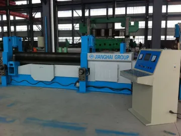 Universal Rolling Machine
-
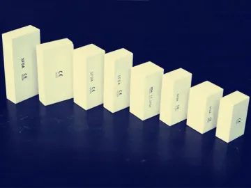 Zirkon Zahn Manual System Compatible Zirconia Block
-
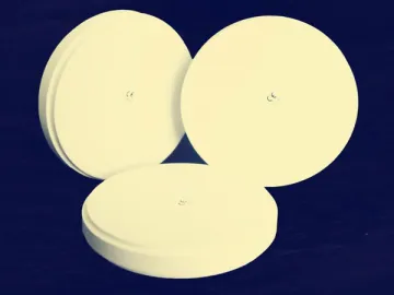 Wieland System Compatible Zirconia Block
-
 CAD/CAM System Compatible Zirconia Disc
-
 Single-Action Drawing Press
-
 CM-MT5 Dental Milling Machine
-
 Dental Alloy
-
 CM-Smart 4 Dental Milling Machine
-
 CM-Smart Manual 5 Dental Milling Machine
-
 Amann Girrbach Manual System Compatible Zirconia Block
-
 Swing Beam Shear
-
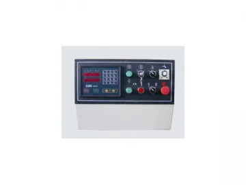 CNC Control Panel for Metal Shear
